
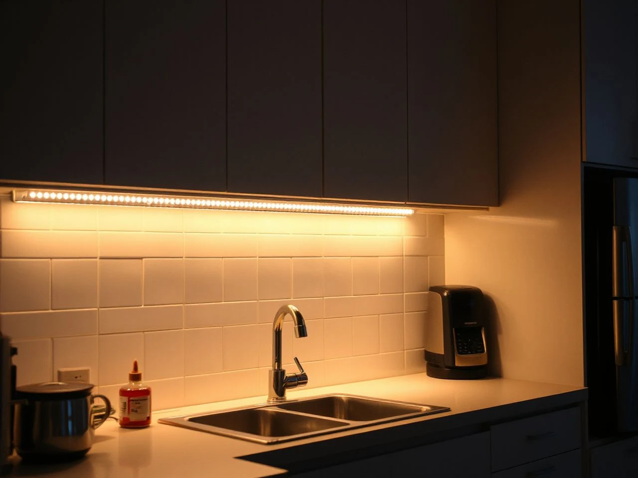
Adding under cabinet lighting is primarily a system-matching and layout problem, not simply a matter of sticking lights beneath a cabinet. The strip, driver, controls, wiring, heat path, and cabinet geometry must work together. The practical distinction is between installing a continuous, concealed light source that distributes task light evenly and installing short, overloaded, or poorly positioned sections that create glare, voltage drop, flicker, and visible bright spots.
I am a lighting obsessive, so I fix most rooms with lamps before touching the furniture. In a kitchen, the same instinct points toward careful light placement rather than decorative hardware. A well-planned LED strip can make a countertop easier to use while keeping the source itself quiet and mostly unseen.
Key Takeaways
- Match the LED strip, driver, dimmer, connectors, and wiring voltage before installation.
- Position the light toward the work surface or backsplash, then conceal the source with cabinet geometry, an aluminum channel, or a diffuser.
- Use marked cut points, protected connections, and a wiring plan that accounts for long runs and voltage drop.
- Use a licensed electrician for new line-voltage wiring, circuit work, or receptacles, especially near sinks and cooking appliances.
Before Adding Under Cabinet Lighting, Plan the Whole System
The first question is not which light looks attractive in a listing. The first question is where power will begin, how the cable will travel, and where the control will sit. A kitchen with separate cabinet runs, a microwave enclosure, open shelving, or a sink interruption needs a different layout from one long uninterrupted row.
Map the cabinet geometry and work areas
Draw the underside of every upper cabinet run. Mark cabinet breaks, wall corners, appliances, the sink, the cooktop, and any place where a backsplash or trim will interrupt the light path. Note where the countertop is glossy, pale, dark, or reflective, because the same exposed LED can look restrained on one surface and harsh on another.
The useful light should generally land across the countertop rather than directly into the eyes of someone standing in the room. A strip positioned too far toward the front edge can produce direct glare, while one pushed too far back can leave the front work area dimmer. The exact position depends on the cabinet depth, the backsplash, and the shape of the counter.
Cabinet geometry determines where an under-cabinet light can distribute task light without becoming a visible glare source. If upper cabinets do not cover the entire work area, the plan may need separate sections or a different source for the exposed portion.
Choose the light character before the hardware
Color temperature, or Correlated Color Temperature (CCT), changes the mood of the room. Warmer light in the approximate 2700–3000K range creates a comfortable, welcoming atmosphere. Cooler light around 4000–5000K resembles daylight and gives the room a more luminous, lively appearance.
For food preparation and material accuracy, pay attention to the Color Rendering Index (CRI). A CRI around 90 or higher generally displays colors with greater vibrancy and precision, which matters when a countertop, backsplash, timber finish, or ingredients need to look as they should.
Task lighting and ambient lighting do not need to use the same visual character. Under-cabinet light can be warmer and calmer in a traditional kitchen, or closer to daylight in a room that already uses cooler ceiling light. I would rather see a modest, consistent CCT across the whole cabinet run than a mixture of color temperatures that makes one section look disconnected.
Decide between a continuous strip and separate fixtures
An LED strip or tape light is suited to a continuous cabinet run because the light source can follow the work surface. Separate short sections may suit divided cabinetry, but each section adds another connector, wire path, and possible bright spot. Small sections can also become overloaded if the driver and wiring were planned for less connected length.
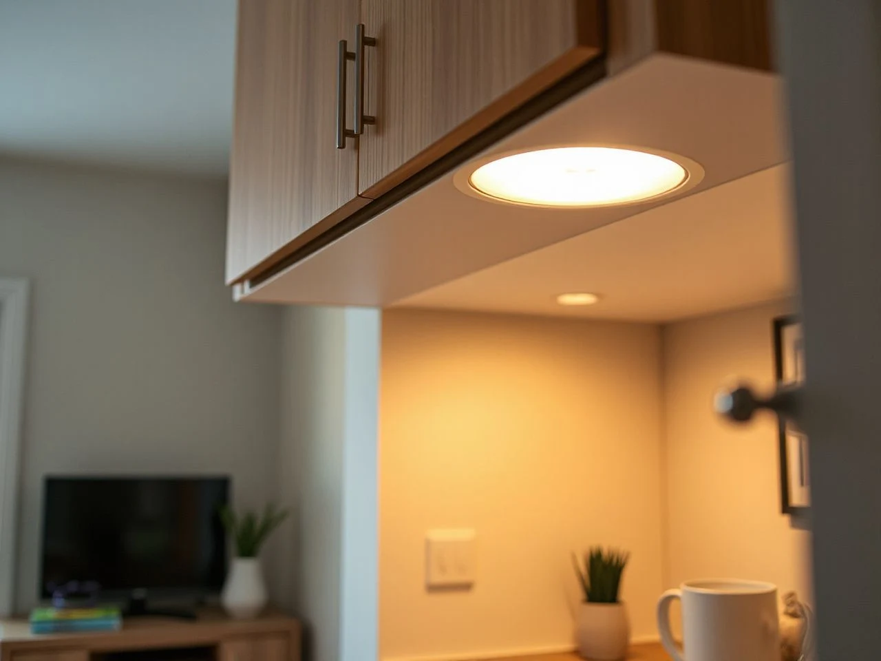
Higher-output LED strips generally need a heat path. An aluminum LED channel gives the strip a suitable mounting surface and can accept a polycarbonate diffuser, which softens the visible points of light and helps conceal the source. A strip should not be left loose against a cabinet when its output and heat requirements call for a channel or another appropriate mounting surface.
Step 1: Match Voltage, Driver Capacity, and Controls
Choose between 12 V DC and 24 V DC
Both 12 V DC and 24 V DC lighting systems can be used for low-voltage LED tape. The important point is that the LED strip, constant-voltage LED driver, dimmer, connectors, and any control equipment must use the same voltage and a compatible control method.
A 12 V strip cannot be connected to a 24 V driver simply because both are described as low voltage. The mismatch can damage the strip or create an unsafe installation. A 24 V system can be useful for a longer planned run because the layout may experience less voltage drop than an equivalent 12 V arrangement, but the exact strip and driver specifications still control the design.
A constant-voltage LED driver must match the strip voltage and have capacity for the entire connected LED load. The driver is the part that converts the available supply for the low-voltage lighting system, so its placement and access deserve as much thought as the strip itself.
Calculate the total connected load
Start with the LED tape specification. The listing should state the electrical load for a given length. Add the load of every connected section, including sections that travel around corners or through cabinet voids. The selected constant-voltage driver must have capacity for that complete connected load rather than only the most visible section.
If the manufacturer does not list the strip’s load per length, the driver cannot be sized responsibly from appearance alone. Do not guess from brightness. Ask for the missing electrical information or choose a system with a complete specification sheet.
Driver capacity is only one part of the calculation. Long runs can experience voltage drop, which may appear as dimmer sections, color variation, or a change in brightness from one end to the other. A wiring layout may need power injection or separate feeds, depending on the strip specification and total run.
Match the dimmer and switching method
A wall switch, inline switch, occupancy sensor, or dimmer can control under-cabinet light, but the control must be compatible with the driver and strip. A control method intended for one type of low-voltage system may not operate another correctly.
Decide whether the lights should operate as one cabinet run or as separate zones. A sink run, prep area, and decorative shelf can be useful as separate zones, but additional zones mean more planning for drivers, cable routing, and controls. The cleanest visible result usually comes from placing the control where a hand can reach it without stretching across the work surface.
The driver should remain accessible for inspection or replacement. Hiding it permanently behind fixed cabinetry may produce a tidy first impression while turning a simple future repair into cabinet removal.
Step 2: Plan Power, Wiring, and Code Requirements
Existing outlet or new electrical work?
An existing outlet may supply a listed low-voltage driver if the installation method, load, location, and local requirements allow it. A new receptacle, a new circuit, line-voltage wiring, or a hardwired switch connection is different work and must follow local electrical code.
New line-voltage wiring and receptacle work should be handled by a licensed electrician when the task exceeds a homeowner’s permitted work or when the wiring will be concealed in walls, connected to a circuit, or located near plumbing and cooking equipment. The electrician can also address inspection requirements and kitchen electrical circuit planning.
Low-voltage does not mean unplanned. Low-voltage cable still needs correct polarity, protected connections, suitable routing, and a path that avoids damage near sinks, cooktops, sharp cabinet edges, and heat sources.
The National Electrical Code includes requirements relevant to wiring methods and electrical installations.
Account for the sink and cooktop
A sink changes the electrical planning because water exposure and nearby receptacles require careful protection. The National Fire Protection Association, which publishes the NEC, provides the governing code framework; local adoption and enforcement determine what applies to a particular installation.
Do not run unprotected cable where it can be pinched by a drawer, cut by a metal cabinet edge, soaked by a leak, or exposed to heat from a cooktop. Keep connections inside suitable enclosures and follow the lighting manufacturer’s routing instructions.
Hide wiring without trapping it
Cabinet backs, side panels, trim, and the backsplash area can hide low-voltage cable, but the route should be planned before the strip is fixed in place. A small cable channel or carefully placed exit can keep wires from sagging below the cabinet. The goal is a controlled route, not a wire pressed into a hinge or tucked where it can be damaged.
For separate cabinet runs, plan where the cable crosses a cabinet joint. Drilling through cabinetry may be possible, but the hole must not damage the cabinet structure, plumbing, or existing wiring. Use suitable bushings or protection where a cable passes through a hole, and leave access to connectors and the driver.
If the kitchen has open shelving, the light source can become part of the visual composition. This is where the distinction between decorative shelves and upper cabinets matters; the guide to Open Shelving vs Upper Cabinets: Top Picks for 2026 can help with the cabinet layout decision before wiring begins.
Step 3: Cut, Join, Mount, and Diffuse the LED Tape
Prepare the mounting surface
LED tape should be installed on a clean, suitable surface. Dust, grease, loose finish, and residue can prevent the strip from sitting correctly. Clean the underside of the cabinet according to the surface manufacturer’s instructions and allow it to dry before mounting.
Measure each cabinet run and mark the starting and ending points before removing adhesive backing. The tape should not be stretched around a sharp corner or forced through a hinge area. Use a suitable connector or a planned cable path for changes in direction.
An aluminum LED channel is especially useful when the strip needs a stable heat path or when the diffuser should sit flush with the cabinet underside. A polycarbonate diffuser can reduce the appearance of individual LED points and soften reflections, but it cannot correct a strip that is aimed directly at the viewer.
Cut only at marked points
LED tape should be cut only at its marked cut points. Cutting between those marks can separate the electrical paths and leave a section unusable. Check polarity marks before joining pieces, because reversing positive and negative connections can stop the section from operating.
Use connectors suited to the strip and its voltage, or make a properly protected connection according to the manufacturer’s instructions. A connector that physically grips the tape is not automatically electrically compatible. Confirm the strip width, contact layout, connector type, and voltage before joining sections.
Plan around voltage drop
Long runs can become dimmer toward the far end or show color variation when the wiring layout does not deliver power evenly. A continuous-looking cabinet run may therefore need multiple feeds, a different connection arrangement, or a 24 V system selected for the planned layout.
Power injection means supplying power to more than one point in a connected run, but the exact method depends on the strip, driver, wire path, and manufacturer instructions. Do not add random parallel wires simply to make a dim section brighter. The polarity, conductor suitability, connection protection, and driver capacity must remain correct across the entire system.
Aim the source at the counter
Position the light toward the countertop or backsplash as appropriate for the task area. A light source close to the cabinet front can reflect strongly from a polished countertop, while a source aimed toward the backsplash may produce a calmer reflected glow. A diffuser helps, but cabinet placement does more of the work.
Test the position before permanent mounting. Temporarily hold the channel or strip in place, switch it on, and look from normal standing positions as well as from the room entrance. Move the source back, forward, or toward the backsplash until the work surface is useful without a direct view of the LEDs.
Step 4: Test, Finish, and Maintain the Installation
Test before closing the route
Connect the system temporarily before hiding cable or fixing the channel permanently. Confirm that every section lights, that the dimmer responds correctly, and that the color remains consistent across the run. Check the ends and connectors rather than assuming a dark section means the entire strip has failed.
Flicker can come from an incompatible dimmer, an unsuitable control method, a poor connection, an overloaded driver, or an unstable power supply. A section that stops working can have a reversed connection, a damaged cut point, a loose connector, or a driver problem. Trace the system from the supply toward the dark section instead of replacing parts at random.
Flickering LED tape usually points to a control, connection, voltage, or driver mismatch rather than a cabinet problem. The listing does not provide a universal troubleshooting sequence, so use the manufacturer’s wiring diagram and specifications for the exact strip and driver.
Finish the visible details
Keep the driver and any serviceable connector accessible but visually quiet. Route cable along a cabinet corner or behind trim where it will not catch on stored items. Avoid a loose loop below the cabinet; it draws the eye and can be pulled during cleaning.
For a wall switch, keep the control aligned with the room’s existing switch layout when practical. An inline switch may suit a small isolated run, while a dimmer is more useful when the same counter serves both food preparation and evening ambient light. The control should be easy to identify without adding a bright indicator that competes with the lighting itself.
Clean the strip and channel carefully
Turn the lighting off before cleaning. Use a soft, dry or lightly damp cloth suited to the cabinet finish, and do not saturate the diffuser, connectors, or exposed electrical parts. Grease near a cooktop should be addressed regularly because buildup can dull the diffuser and make the light appear uneven.
Do not pull the strip away from the cabinet to clean behind it. If the adhesive has failed, the strip is lifting, or the diffuser has clouded or cracked, repair the mounting system rather than pressing the tape back into a dirty surface.
Repair or replace?
A loose connector, incorrect polarity, or a failed control may be repairable when the strip itself remains in good condition. A damaged strip with repeated dark sections, visible heat damage, or failed adhesive may be more practical to replace than to splice repeatedly. The same applies to a driver that is correctly supplied but no longer produces stable output.
Replace the driver only with one that matches the strip’s voltage, connected load, and control method. Replacing a 12 V driver with a 24 V unit, or pairing a new driver with an incompatible dimmer, simply moves the original fault to another part of the system.
Common Problems and Their Direct Fixes
Some sections are dimmer
Uneven brightness usually calls for a review of run length, connection points, wire routing, and voltage drop. Check whether the far section receives power through a long narrow path or through a connector that does not make reliable contact. A separate feed or power injection may be appropriate if the strip instructions support it.
Sections have different colors
Color variation can result from mixing strips with different CCT specifications, using sections from different production batches, or allowing voltage drop to affect a long run. Keep the same specified CCT across a visible cabinet run and test all sections together before permanent installation.
The countertop shows bright dots
Bright dots usually mean the LEDs are visible or reflected directly from the work surface. Reposition the strip toward the backsplash, conceal it beneath the cabinet lip, or add an aluminum channel with a polycarbonate diffuser. A diffuser can soften the appearance, but a poor viewing angle still needs correction.
The lights overheat
Heat management depends on the strip’s output, mounting surface, and installation instructions. A higher-output strip left loose against a cabinet may lack the suitable heat path provided by an aluminum LED channel. Check the manufacturer’s requirements rather than treating adhesive as a substitute for thermal mounting.
The lights work without dimming
A dimmer that switches the lights on but will not dim them may use an incompatible control method, or the driver may not support that control. Confirm whether the system expects a low-voltage dimmer, a compatible wall dimmer, or another specified control arrangement.
Frequently Asked Questions
What type of light works best for my cabinet layout and countertop?
A continuous LED strip or tape light usually suits a long uninterrupted cabinet run because it distributes light along the work surface. Divided cabinetry may need separate sections with planned feeds. For glossy counters, conceal the source, aim it toward the backsplash, and use a polycarbonate diffuser when individual LED points remain visible.
Should I use a 12 V or 24 V under-cabinet lighting system?
Either can work when the strip, constant-voltage driver, dimmer, connectors, and wiring all match. A 24 V layout may experience less voltage drop across a longer planned run, but the manufacturer’s specifications determine the acceptable length and connection method. Do not connect a 12 V strip to a 24 V driver.
How do I size the driver for the full LED tape run?
Use the strip specification for its load over a stated length, then add every connected section, including sections joined around cabinet breaks. Select a constant-voltage driver with capacity for the complete connected load and the same voltage as the tape. If the strip’s load is missing from the listing, do not guess; obtain the specification first.
Can I connect under-cabinet lights to an existing outlet?
An existing outlet may supply a suitable low-voltage driver when the installation complies with local code and the location is appropriate. New receptacles, circuits, concealed line-voltage wiring, and hardwired switch connections should be planned with a licensed electrician.
Why do some LED sections flicker or show different colors?
Common causes include an incompatible dimmer, a mismatched driver, loose or reversed connectors, voltage drop on a long run, and mixed CCT specifications. Turn off power before inspecting connections. Check the system from the driver outward, verify polarity, confirm the control method, and follow the strip manufacturer’s wiring diagram.
How do I hide wires without making the installation look unfinished?
Plan the cable route before mounting the tape. Use cabinet sides, trim, or a suitable channel while keeping connectors and the driver accessible. Protect cable where it passes through cabinetry, keep it away from hinges and heat, and avoid leaving loose loops below the cabinet. A visible but straight, protected route looks better than a hidden cable that can be pinched.
Can LED tape be cut and extended?
LED tape can be cut only at its marked cut points. Join sections with connectors that match the strip’s voltage, width, contact layout, and connection method, or make a protected connection according to the instructions. Long extensions may need separate feeds or power injection because voltage drop can cause dimming and color variation.
When should I replace the strip or driver instead of repairing it?
Repair a loose connector or incorrect control when the strip remains intact and the fault is clear. Replacement becomes more practical when the tape has repeated failed sections, heat damage, damaged cut points, or failed mounting. Replace the driver only with a unit that matches voltage, total load, and dimming method.
Do under-cabinet lights need special clearance near a sink or cooktop?
There is no single clearance rule that covers every cabinet, appliance, wiring method, and local code requirement. Keep connections protected, route cable away from water and heat, and confirm GFCI requirements where applicable. New line-voltage work near a sink or cooktop belongs with a licensed electrician who can apply the locally adopted code.